Gas Treatment
Reducing CO2 in the maritime industry with OASE®
Did you know?
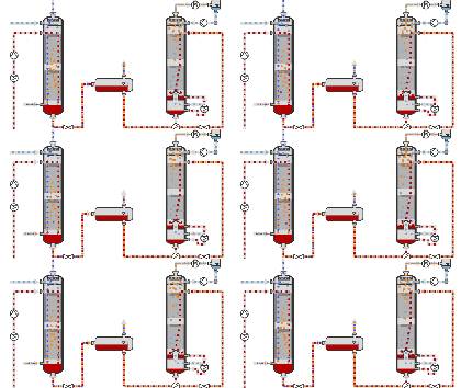
Fig. 1: This figure shows an example of the key equipment used in a gas scrubbing process for the removal of CO2 at increased pressure, such as when purifying natural gases. In the absorption column (left-hand column), the gas to be purified flows from bottom to top, coming into contact with the scrubbing liquid in the countercurrent flow. The scrubbing liquid loaded with CO2 is unloaded in a decompression stage (center) and in a regeneration column (right) and is fed back into the absorption column. Source: BASF SE.
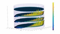
Fig. 2: This three-dimensional diagram shows the calculation result of BASF’s CFD model of the maldistribution of liquid as a function of the column height. The further the liquid from above runs down through the column internals, the greater the liquid maldistribution becomes. Source: BASF SE.
